A DIY resistive ribbon sensor
by Johannes Taelman
Context
| ABSTRACT | |
|
Tactile and multi-handed user-interfaces are a fascinating and active topic of research. We explain how a resistive ribbon sensor can be constructed, how it works, and how it can be deployed. |
Recommended prior knowledge
- Elementary electric circuits
- Ohm's law
- Kirchoff's laws
- Basic electronic circuit diagram conventions
- Simple electric measurements
- Basic soldering
Ribbon sensor
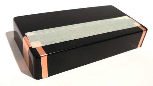
A resistive ribbon sensor is constructed as a stack of tapes and adhesives. One layer has resistive properties. Another layer (separated from the resistive layer by an air-gap) is a conductor. Pushing on the ribbon will create conductive contact between the resistive strip and the conductive strip.
When one finger pushes the ribbon, the ribbon can be compared to a potentiometer. At rest, the resistive strip makes no contact.
Construction materials
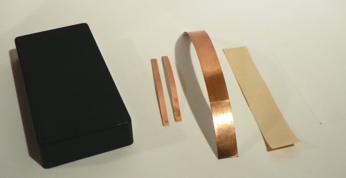
This is the list of materials needed to construct this ribbon:
- Adhesive copper tape, 12.7mm wide: Available from electronic parts distributors, I used Chomerics CCH-18-101-0050
- Double-sided adhesive tape, 19mm wide
- PVC (electrical) tape, 19mm wide
- Resistive (8mm video) tape: Not all videotape has resistive properties, and not both sides are resistive. Test it with a multimeter. My tape measures about 15 kiloOhm/square (so a strip of 80mm long measures 150kOhm between the ends). All kind of tapes stand a chance to be resistive. But audiocassette tape is a bit small. VHS, 8mm, or audio reel-to-reel tape are better candidates.
- Transparency sheet or plastic document sleeve
- Plastic enclosure: to contain the electronics (Arduino or something else), and as rigid base for the ribbon sensor.
Construction
The resistive tape is pushed against the copper tape by the finger pressure. At the ends of the resistive tape, two terminals are attached.Step 1: Place copper foil on top of the box
It can be folded around to the inner side of the enclosure to provide connection without running a wire from inside the enclosure to outside.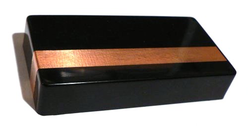
Step 2: Cut and place spacer
I used adhesive PVC electrical tape as spacer. The purpose of the spacer is to create a gap between the resistive tape and the copper tape when there is no pressure on the ribbon sensor. Other sorts of tape can work too, but it needs to be thicker than standard office tape to make a reliable gap. PVC tape is a bit difficult too cut since it distorts easily. Sticking it on a piece of adhesive-protection-tape (like found on double-sided tape) makes it easier to manipulate, and it is easy to peel it off. The width of the slot I cut out is 6mm, a bit less than the width of the resistive tape.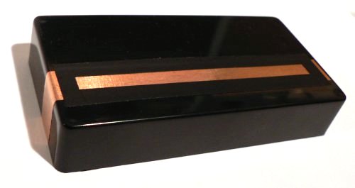
Step 3: Placing the end-terminals
Adhesive copper tape serves this purpose nicely. I cut 4mm wide strips out of the tape. The adhesive side goes on the spacer and enclosure. The resistive tape will make contact with these pieces of tape without adhesive.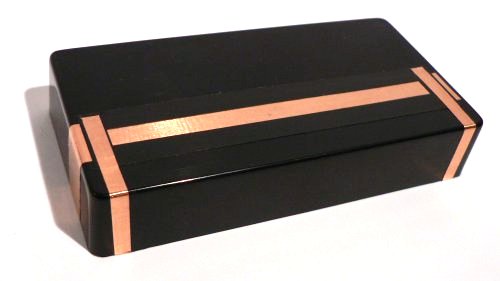
Step 4: Build and place the top part
To give the resistive tape strength, it is sandwiched by the use of double-sided
sticky tape to a stronger but flexible plastic. This is build in top-down
order. I cut a 19mm wide strip out of a transparent document sleeve. This is
fully covered with the double-sided sticky tape. And on top of that the
resistive tape is mounted - resistive side up (exposed). This assembly can
now be sticked on the enclosure.
Almost ready...
Step 5: Cover exposed copper
It is a good idea to cover all exposed copper tape with some other non-conductive tape. Otherwise, touching exposed copper tape will inject unwanted noise.
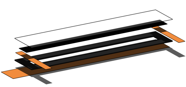
Here's an exploded view of the ribbon sensor construction:
First tests
Measure the resistance between the two end terminals. This is expected to read out a constant resistance if the sensor is not touched.Measure the resistance between one end terminal and the bottom copper strip. If not touched this expected to be a open circuit (infinite resistance). If this is not working out, use a stiffer plastic for the top layer or a thicker spacer material. Maybe sandwich two layers of tape for the spacer.
When the sensor is touched, different resistances can be measured between the bottom copper strip and the end-terminals, depending on the place where you touch it.
Circuit
Remember Poullet's law? Resistance of a bar of a certain resistive material is proportional to length, and inverse proportional to area of its section. So, double the length (keeping all other things the same) and the resistance doubles too. Double the width of a tape, and the resistance halves. So for a tape (constant thickness) every square shape, large or small, has the same resistance - depending on the thickness and material of the resistor.
Simple, bad version
symbols:
- VDD is positive supply voltage (5V on an arduino, 3.3V on some others)
- GND is ground
Here is a schematic view of the ribbon sensor:
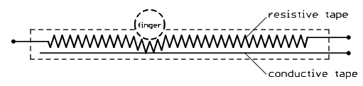
Let's call the total resistance of the resistive tape RT. Using
the ribbon sensor as a pure resistive divider is tempting:
Hey it's just like a regular potentiometer:
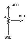
The conductive strip serves as a tap point. The voltage on this tap point will
vary proportionally (linear) depending on the location of touch point. But when
the ribbon sensor is touched at both ends, it almost short circuits the supply.
And when the ribbon is not touched, the tap point is floating:
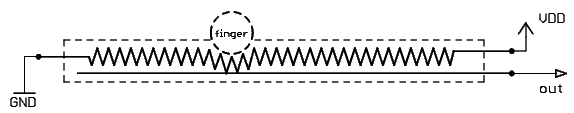
Better, multi-touch version
Grounding the conductive strip, and adding external resistors (R1 and
R1) to the 2 end-terminals of the sensor allows to read more
information from the sensor:
At rest the end-terminals are pulled to supply voltage by the two external resistors:
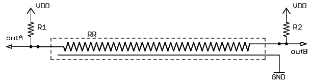
So both
OutA as OutA
will measure VDD (supply voltage) in this case.
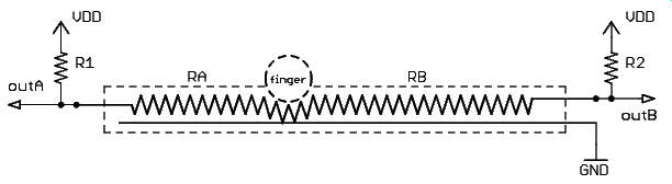
When touched at one spot there are two independent resistive dividers formed.
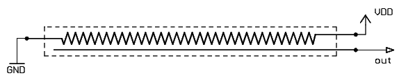
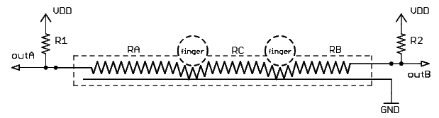
Or unfolded schematic:
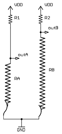
The resistive divider that makes up the voltage of OutA consists
of R1 and RA. The value of RA is linear
proportional to the distance of the touch point to the left side of the ribbon
sensor. We can equate the voltage on OutA to:
VOutA = VDD
|
|
OutB:
VOutB = VDD
|
|
RA and VOutA
is non-linear.
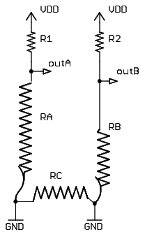
When the ribbon is touched on two places, the same equations are still valid.
But the sum of RA and RB is no longer the total
resistance of the resistive tape:
Unfolded:
Adding a finger in between the previous two touches does not affect the
situation electrically:
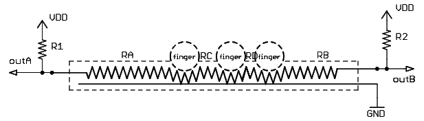
Resistors between two points at the same voltage (here: ground to ground) do
not do anything.
So now we have a ribbon sensor in a circuit where we can measure a voltage that depends solely on the leftmost and the rightmost contactpoint.
Math
We need to obtain the relation from measured voltage atVOutA
or VOutB to RA or RB.
VOutA * (R1 + RA) = VDD * RA

				VOutA * R1 + VOutA * RA = VDD * RA

				VOutA * R1 = VDD * RA - VOutA * RA

				VOutA * R1 = (VDD - VOutA) * RA

				VOutA * R1 / (VDD - VOutA) = RA

				RA = VOutA * R1 / (VDD - VOutA)
Likewise for VOutB:
RB = VOutB * R2 / (VDD - VOutB)
What value do we take for R1 and R2
?
There is no reason to take different values for R1 and R2,
that would break symmetry.
The maximal voltage we can find on outA is when the ribbon is
actuated at the rightmost position, meaning RA = RT. This voltage
should not be too low, since the A/D converter measures the range from 0V (GND)
to 5V (VDD) (VDD could also be a different voltage but that does not make any
difference) is divided in, say, 1024 steps (for a 10-bit Analog-to-Digital
converter). If the maximum voltage on outA is only 5% of VDD,
we can measure only 51 different steps. This keeps us from using a very large
resistance for R1 and R2.
On the other side, if we take a very small resistance for R1 and
R2, half of the voltage travel will occur in a small zone of the
ribbon near the terminals.
If both distances add up to the total length of the ribbon, we know that there is only one touchpoint. However this is not completely correct: a single touchpoint will have a non-zero width. But an acceptable threshold can be found to separate the two touchpoints situation from one touchpoint situation.
Pure data
Lets assume that you have your ribbon sensor connected to pure data via some kind of interface (arduino, wisebox, roll your own ...). The ground of the interface is connected to the conductive strip, the two ends of the resistive strip both connected to an analoge-to-digital conversion input and a resistor to the supply voltage. You are getting the data into pure-data, how exactly depends on the type of interface used. Better resolution than 7bit MIDI is strongly recommended.
Linearize voltage to distance
Now, let's patch the conversion from voltage to linear distance. Remember this equation derived above:
RA = VOutA * R1 / (VDD - VOutA)
Let's forget the standard units (ohms, volts), we can do that if we use the same 'new' unit everywhere. Lets express voltage in Analog-to-Digital conversion units (1023 units is 5V for arduino).
RA = VOutA * R1 / (1023 - VOutA)
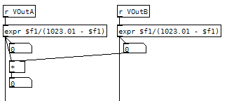
R1 is constant. If we use the expression [expr $f1 / (1023 - $f1)] we
obtain a value that is proportional to RA. And remember RA
is proportional to the length of the corresponding piece of resistive tape. If
untouched, outA is at VDD, so this expression will give 1023 / (1023 -
1023)! A division by zero occurs... It's wide to prevent this from happening.
Using the expression [expr $f1 / (1023.1 - $f1)] will give a small
error when touched, and a very large but finite value (10230) when untouched.
The same expression can be used for the other side. But this time the zero point is on the other side of the ribbon.
Identifying the situation
It's usefull to detect the different situations: no touch, single point, dual point. When the results of both expressions are added, these three cases can easily be separated:- no touch: very large value (20460?)
- single touch: total length of the sensor (independent from where it is touched) minus a tiny bit.
- dual touch: below the total length of the sensor (independent from where it is touched).
Play
Similar constructions can be made in Max or other environments, but remind that you should suffix all numbers here with a point, otherwise Max will do integer (whole numbers) math, giving undesired rounding effects.
Now you can start exploring connecting the outputs to sound.
Small excercise: connect the leftmost touchpoint distance to the frequency of a square-wave oscillator, and the rightmost distance to the cutoff of a resonant low-pass filter. Mute the oscillator when there is no touch. The filter will now always be tuned at or above the fundamental frequency of the squarewave - there is nothing to filter below the fundamental anyway. Now you can play filter-swept ribbon-theremin. Maybe quantize the pitch to a nice scale. Use a few buttons to select different scales. A new no-guitar hero is born!
Ideas for future work
- Make a small 2D resistive touchpad from one inch wide tape (used on music studio multitrack reel-to-reel recorders, studio video tape, and probably also old computer storage)
- Use a custom PCB as base material instead of sticking copper tape on a plastic enclosure. It'd better be gold-finished than the rusty tin finish you get standard nowadays though. Useful for a multi-ribbon controller device, maybe with USB + microcontroller on the backside...
- Add some sort of relief to the top layer, to add some tactile features. Could be a guitar string taped on the top-side to guide your finger in the dark.
- Some way to give it a snap-action feel? Beveling the top-layer?
References
- R. Koehly, D. Curtil, M. Wanderley, Paper FSRs and Latex/Fabric Traction Sensors: Methods for the Development of Home-Made Touch Sensors Proceedings of the 2006 International Conference on New Interfaces for Musical Expression (NIME06), Paris, France
- Ribbon Controller
- http://www.geocities.com/tpe123/folkurban/synthstick/synthstick.html